project-team-turbo-housing

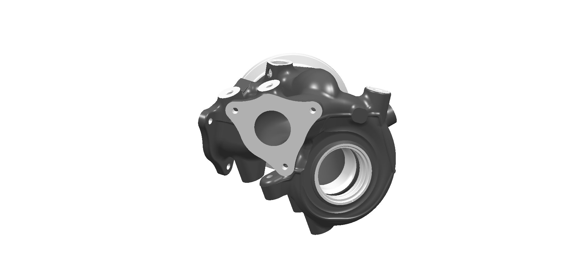
PROJECT TEAM · PRACTICAL EXAMPLE

Turbocharger Housing

Complete machining solution for a turbocharger housing across multiple machines and operations.

Overview

Complete machining solution for a turbocharger housing across multiple machines and operations.

Objective

Optimise the entire production process to achieve high productivity, process stability, and reduced cycle time.

Turbocharger Housing

Key Facts

• Material: Heat-resistant alloy (DIN 1.4837 + Nb)

• Multi-machine production line

• Complex multi-operation component

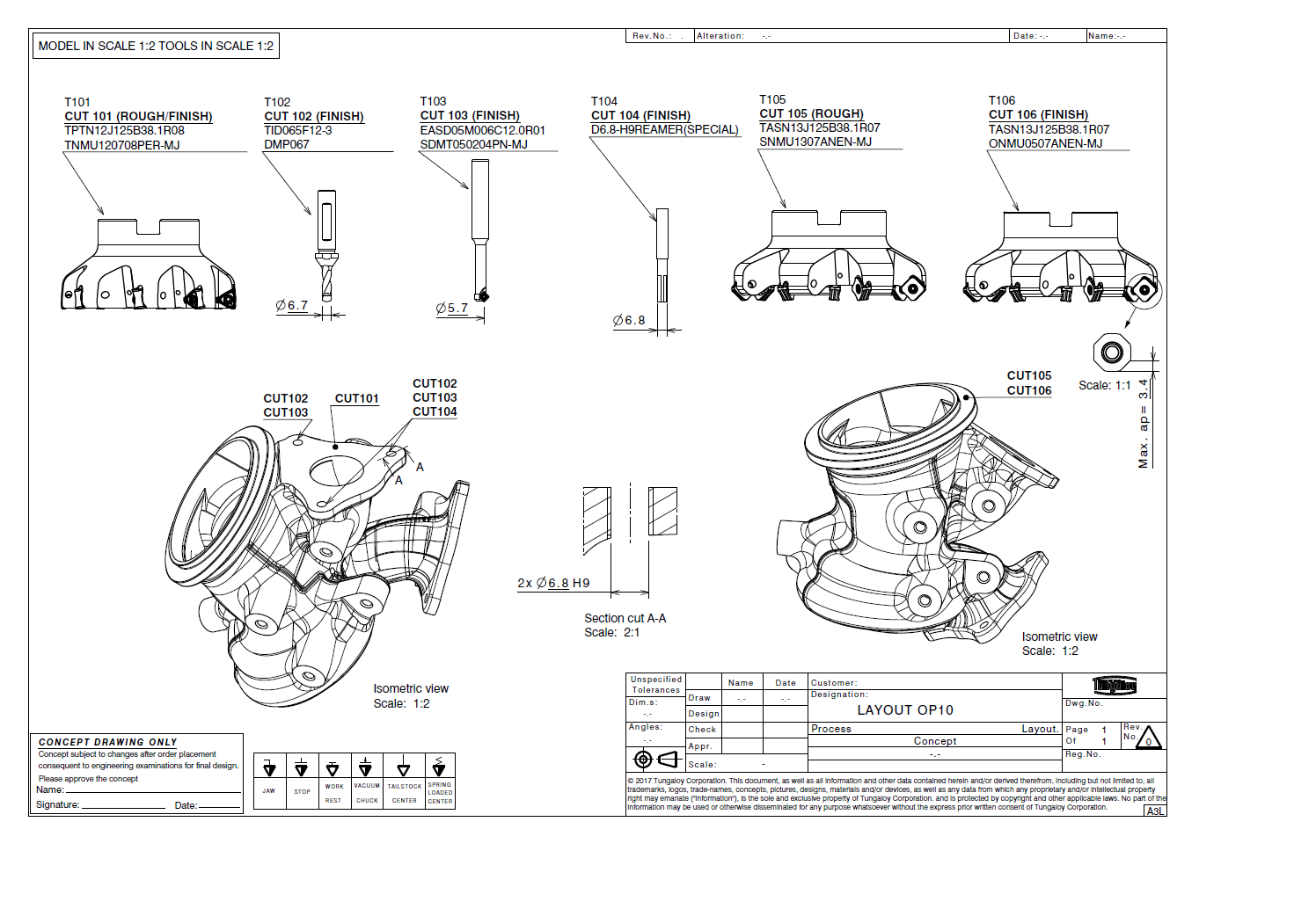
OPERATION 10

3-Axis Machining

Operation 10 Diagram

Initial Machining

• Flange surface machining

• Exhaust outlet facing

• Preparation of key reference areas

Key Highlights

• Stable roughing strategy

• Optimised tool engagement

• High material removal efficiency

PROCESS OPTIMISATION SUMMARY

Multi-Stage Machining, Operation by Operation

OP Description N.O.P New Tool Time (min)
OP10 Flange surface and exhaust outlet end face 6 6 2.066
OP20 Bore, inner and outer machining 9 8 4.393
OP30 Flange B, side boss hole 4 4 7.622
OP40 V-band end face O.D. machining 6 6 2.382
OP50 Flange A, thread, side boss facing 6 6 1.104
Bushing holes and valve mounting surface 6 6 1.043
Side boss surface 4 4 2.157
Total 41 40 20.767

Process Overview

• Multi-stage machining process

• Optimised sequence across operations

• Balanced tool utilisation

Key Results

• Reduced overall machining time

• Optimised number of tools and operations

• Improved process efficiency across all stages

Result

Total Optimised Cycle Time: 20 min 46 sec

Have a Similar Component?

← Back to Project Team Start a Project Review →